Journal of Civil, Structural and Transportation Engineering (JCSTE)

Volume 2 - Year 2016 - Pages 7-11
DOI: TBA
Results of Experimental Tests on Composite Beams
Vincent Kvocak, Daniel Dubecky
Technical
University of Kosice,
Department of Civil Engineering,
Vysokoskolska
4, Kosice, 042 00, Slovakia
vincent.kvocak@tuke.sk; daniel.dubecky@tuke.sk
Abstract - The paper presented focuses on the research into progressive bridges with encased filler beams of modified steel sections designed to minimize steel consumption without affecting essentially the overall structure resistance. This type of construction is suitable for bridges over short and middle spans as it offers a number of advantages, such as little headroom, quite clear static action of forces and a short construction period with no falsework required. Among some disadvantages is the economic inefficiency of steel I-sections, which are employed in the majority of bridges of this type. Therefore, there is an urgent need for the development of more economical design approaches and more purposeful arrangement and employment of steel beams. The paper presented brings some results from experimental tests on elements with encased steel filler-beams acting compositely under both short-term static and dynamic loads, and long-term load.
Keywords: Composite beams, experimental tests.
© Copyright 2016 Authors - This is an Open Access article published under the Creative Commons Attribution License terms. Unrestricted use, distribution, and reproduction in any medium are permitted, provided the original work is properly cited.
Date Received: 2015-06-23
Date Accepted: 2016-04-01
Date Published: 2016-06-09
1. Introduction
Composite steel-concrete structures are more and more commonly employed in both structural theory and construction practice. The two materials in combination allow the exploitation of positive physical properties of both materials, i.e. those of concrete acting effectively in compression and steel in tension, making the resulting structure stronger than it would be obtained by merely adding their strengths [1]. One of the commonest types of composites is a deck bridge with encased filler beams [2]. Deck bridges with such beams have been used in Slovakia and other European countries without any major change since the beginning of the 19th century. Their static action is perfectly comprehensible, structural solution simple, construction period reasonably short, and the maintenance easy. Their main disadvantage is cost-ineffectiveness. To date, deck bridges are designed in compliance with STN EN 1994-2 - the standard currently in force - which allows only for rolled and welded beams of a constant cross-section corresponding to I- or H-sections in their shape and dimensions [3]. These rolled-steel sections are placed on bridges supports and are encased in concrete. Concrete acts compositely with steel sections in the compression zone of the deck, stiffens it, and perfectly prevents the deck from local and global instability, i.e. the structure is laterally restrained against buckling. At the same time, concrete protects such beams against corrosion, so they do not need to be painted and the paint renovated.
The deck with encased filler beams can be easily manufactured and has very little structural height. However, the one big drawback with the deck is relatively high steel consumption due to the symmetry of rolled I-sections and the necessity of placing such sections in sufficient quantity and closeness in the deck. Verification and structural design of deck bridges with modified sections is not specified in current standards. No detailed methodology is available, neither are construction procedures for deck bridges. The idea to supplement the missing data and the effort to employ steel sections in a more effective manner have led the authors of this paper to the development of a steel section that would act prevailingly in the tension zone of the future composite bridge. A variety of steel sections were included in the research study ranging from T-sections with various methods of composite action to perforated hollow sections [4].
2. Alternative design solution for deck bridges
The first series of specimens using modified steel sections has been already tested in the laboratories of the Institute of Structural Engineering at the Civil Engineering Faculty of the Technical University in Kosice [5]. The main goal was to design and experimentally verify deck bridges with encased filler beams made of modified sections and achieve major economies in steel consumption. A new modified shape of steel section was designed in the Institute of Structural Engineering of the Civil Engineering Faculty at the Technical University in Kosice in which all the knowledge acquired in the previous research had been applied[6]. The specimen can transmit the self-weight of fresh concrete in the construction phase without any falsework. The method of interconnection to transfer shear between the steel and concrete elements improved as well; therefore, there is no slip at the steel-concrete interface in the loading stage. Rigid load-bearing reinforcement in the experimental specimen N1 was designed as a welded hollow section. The hollow section was made by welding a 6 mm thick U-shaped steel sheet forming the top flange and webs of a section to another 6 mm thick steel sheet forming the bottom flange with overhanging ends. Holes 50 mm in diameter were cut by flame in the webs at an axial distance of 100 mm. Transverse reinforcement bars 12 mm in diameter were threaded through every third hole in the beam. In addition, the top flange was perforated by holes 50 mm in diameter at an axial distance of 100 mm. All the holes were arranged in such a manner that they appeared alternatively in the web or flange of each section. The transverse and longitudinal sections of Beam N1 are given in Figure 1.
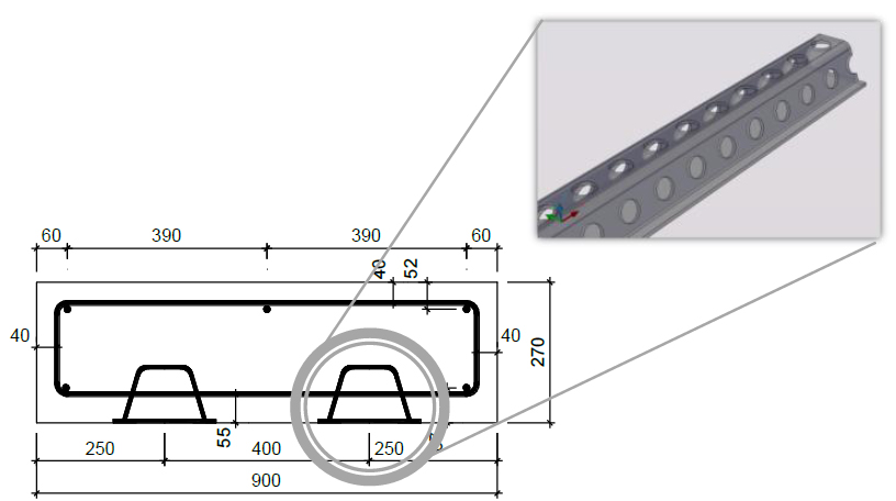
The overall width of the specimens was 900 mm, the height 270 mm and the length 6000 mm. The theoretical span was 5800 mm. Every specimen contained two beams. In the longitudinal direction, the edges of the beam were fixed with reinforcement bars 12 mm in diameter to provide stability and ensure co-action with the transverse reinforcement [5].
3. Static Loading Tests
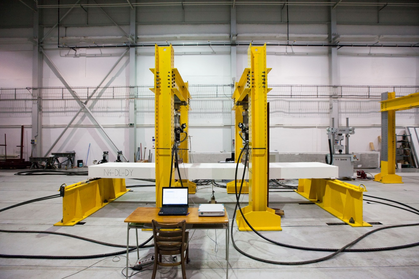
During the concreting phase the specimens were placed on a solid base, so the zero loading state corresponded to the dead weight of the beams. The specimen was loaded by vertical forces applied at a distance of 2000 mm from both edges; the axial distance between the forces being 1800 mm and a free end overhanging the support 100 mm (Figure 2).
All the laboratory tests were carried out and the specimens manufactured in the laboratories of the Institute of Structural Engineering. The specimens were symmetrically loaded by means of hydraulic presses so that pure bending occurred in the section between the presses. Zero loading corresponded to the dead weight of the beams. Another loading procedure was carried out, the pressure in the hydraulic presses incrementally increased to 10 bars, which equalled approximately 15 kN. The specimens were unloaded twice.
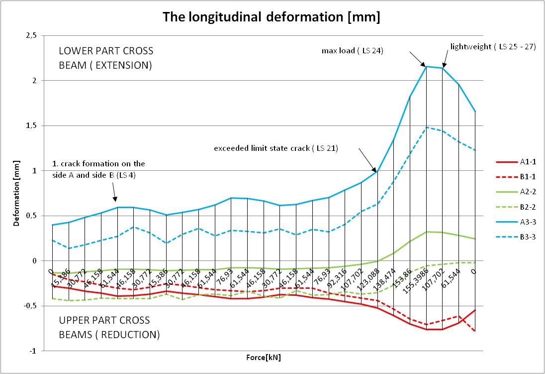
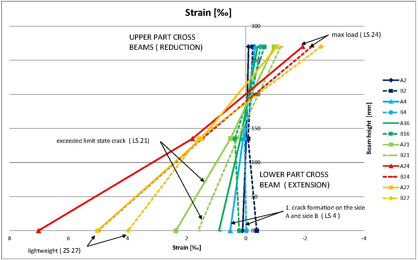
Once the tensile strength of the concrete was exceeded hairline cracks began to emerge. These cracks are further opened and Increase magnification to reach a length of about 200 mm, which is the estimated position of plastic neutral axis. The tests were completed, it was not possible to increase the load transmitted samples. There was a significant idening of deflection without increasing the load. Dependence longitudinal concrete strains on size of load is plotted in the graph in Figure 3. On this chart is readable break, which was exceeded limit state cracks and also the culmination of the burden of its maximum value and the subsequent lightweight.
Strain (relative deformation) was measured and recorded by means of strain gauges situated at the points most subjected to bending and those in the areas around holes. Inductive sensors detected the mid-span deflection and sinking in the supports. The correlation between the maximum deflection and load (force) applied is shown in Figure 4.
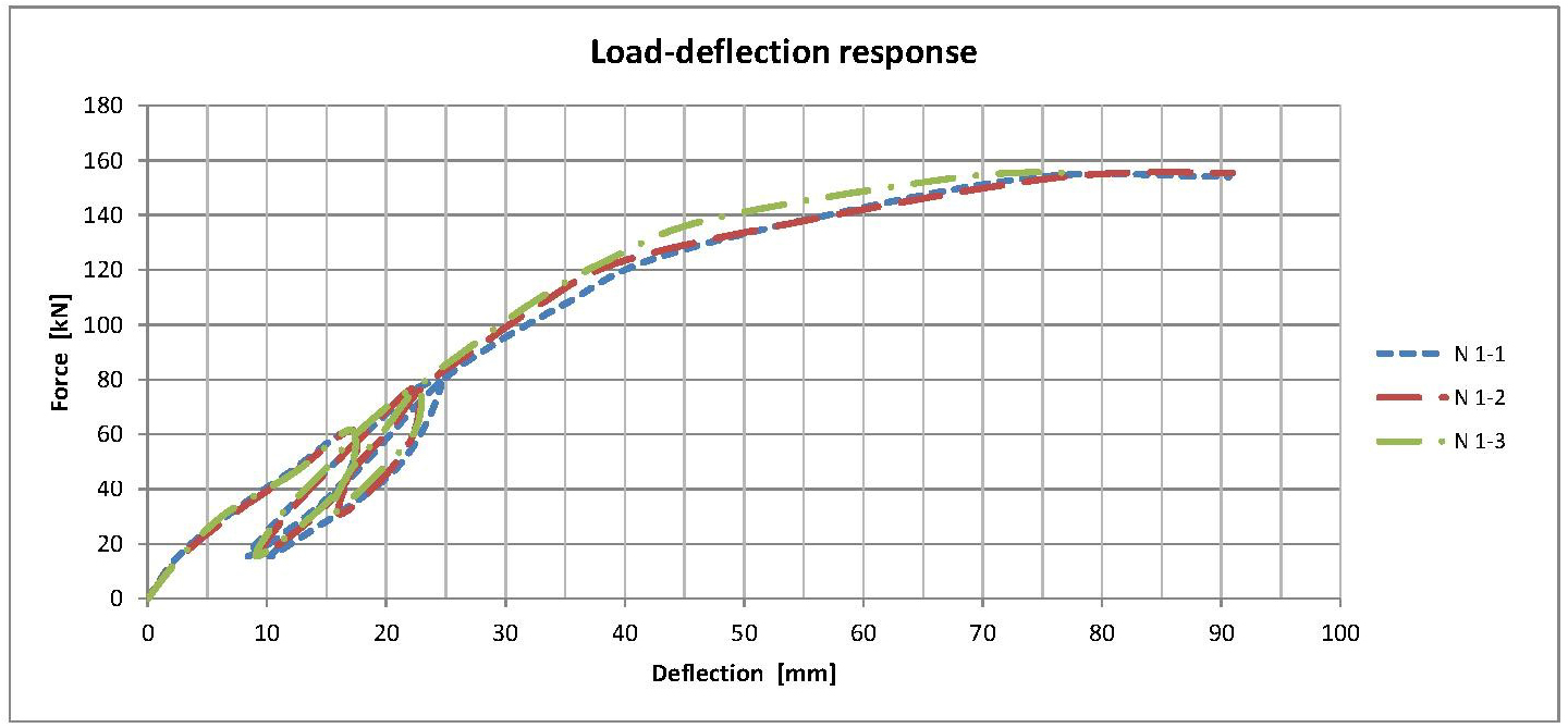
The graph above represents the correlation between the deflection and loading force in the specimen of a composite beam. The beam was unloaded at the loads of 60kN and 80kN, and even though there was no further external load applied, severe permanent deformation in the beam remained.
There was sufficient composite action/shear connection between the steel and concrete elements of the section, which is illustrated by the graph itself. There was no substantial increase in deflection that would otherwise have occurred providing that the composite action between the elements had failed.
It can be concluded from the experiment that the neutral axis/plane in the beam tends to move towards the upper compressed fibres, which is close to the assumptions made.
4. Fatigue Loading Tests
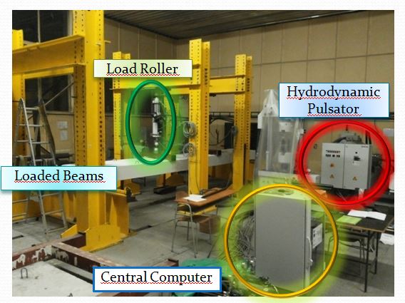
Fatigue tests on the experimental beams took place on breaking equipment, the same equipment which was used for short-term tests with quasi-static loads. The specimens were symmetrically loaded by means of hydraulic presses so that pure bending occurred in the section between the presses. The axial distance between the two hydraulic cylinders was 1800 mm and the distance from the supports 2000 mm. All test arrangements are given in Figure 6.
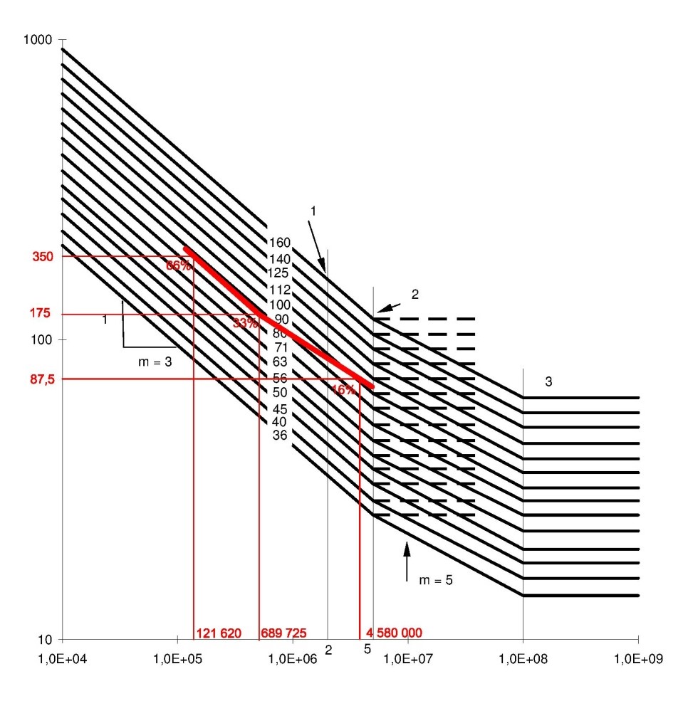
Fatigue tests were carried out on ten
beams. One set of beams was subjected to variable loads ranging from -10 kN to
-90 kN per one cylinder corresponding to approximately 66% of their theoretical
load-carrying capacity and a stress range ![]() .
Another set of beams was loaded within the range of stress from -10 kN to -50
kN corresponding to approximately 33% of their load-carrying capacity and a
stress range
.
Another set of beams was loaded within the range of stress from -10 kN to -50
kN corresponding to approximately 33% of their load-carrying capacity and a
stress range ![]() . Some other beams were
subjected to long-term loads corresponding to 16% of their loading capacity and
a stress range
. Some other beams were
subjected to long-term loads corresponding to 16% of their loading capacity and
a stress range ![]() . They have been loaded by
variable loads, the stress range per one hydraulic cylinder oscillating between
-10 kN and -30 kN. The failure of the
beams was owing to a fatigue crack in the encased steel section approximately at
the point of loading. The results from fatigue tests on the composite beam are
shown in Figure 7.
. They have been loaded by
variable loads, the stress range per one hydraulic cylinder oscillating between
-10 kN and -30 kN. The failure of the
beams was owing to a fatigue crack in the encased steel section approximately at
the point of loading. The results from fatigue tests on the composite beam are
shown in Figure 7.
5. Long - Term Loading Tests
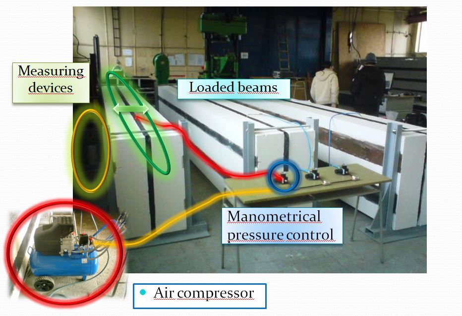
Long-term tests started at the laboratories of the Institute of the Civil Engineering Faculty in Kosice in 2012 and they are planned to be completed in 2016 [7]. During these tests the specimens are placed on their sides. There are two specimens making a pair of beams supported and loaded simultaneously. The beams are turned with their top flanges facing each other at a distance of 50 mm. The support structure consists of frames which compress the beams against each other at their theoretical supports. Compression load is exerted using air pillows located in the gap between the beams. The load activated in such a manner remains continuously uniform all over the top surface of the beam. The constant pressure in the pillow is maintained with an air compressor connected through valves to air pressure gauges. It is possible to set a specific pressure for each pillow.
The specimens were loaded by small incremental advances of 5 kPa to reach the final pressure of 30 kPa in N1 Beams and 25 kPa in the other beams. The long-term pressure applied to the specimens corresponds to as much as 40% of their bending resistance. Deflection is measured separately in the beams stored on the right- hand rack (N1-4) and the left-hand rack (N1-5) (Fig. 9).
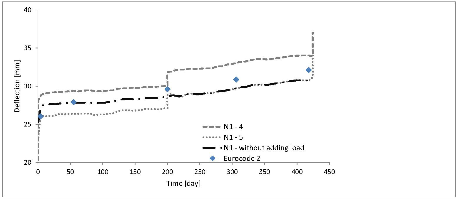
The graph in Figure 9 shows the relationship between deflection and time. It represents the gradually increasing permanent deformation of the beam under continuous load (i.e. creep) exerted by means of the air pillow. The deflections in the beam increased sharply at the initial stage of loading. When the beam stabilised over time, the increase in deflection became very modest. The test will continue by adding more load to the beams and, after the consolidation, the load will be increased for the third time. It will be possible to observe time-and-load-dependent rheological changes in the beam.
6. Conclusions
The first step in the experimental research was to perform static tests under short-term loading. The moments of resistance at the yield point of the steel in three specimens were determined by the experiments. The moment values measured exceeded the theoretical resistance in all specimens. The average margin in resistance was approximately 6.48%. Great deflection was observed at the stage of reaching the plastic moment of resistance. Upon unloading, residual deflection was detected due to the changed bending stiffness after cracking occurred in the concrete. Another series of experiments presents long-term loading tests. Specimens of composite beams have been subjected to continuous long-term load. Deflection and strain of the steel flange and concrete at the mid-span of the beam have been recorded during the ongoing experiment. After the completion of the experiment these long-term measurements will be used for the evaluation of creep in the beams. The dynamic experimental measurements will be then compared with the results obtained by means of the computational models using the software program ABAQUS in the future. Based on this comparison, it will be possible to make some generalizations regarding the methods of calculation for a variety of beam spans.
Acknowledgement
The paper was supported from the project ITMS: 26220220124 "Development of Bridges with Encased Filler Beams of Modified Shapes".
References
[1] B. Bell, "Sustainable Bridges - Assessment for Future Traffic Demands and Longer Lives," European Railway Bridge Demography. View Article
[2] J. Odrobiňàk, J. Bujňàk and J. Žilka, "Study on short span deck bridges with encased steel beams," in 23rd Czech and Slovak International Conference on Steel structures and bridges, Czech Republic, 2012. View Article
[3] STN EN 1994-1-1: Eurokód 4., "Proposal of composite steel and concrete constructions. Part 1-1: General regulations and regulations for bridges," SUTN Bratislava, 2006. View Article
[4] V. Kvočàk, V. Kožlejovà and D. Dubecký, "Analysis of Encased Steel Beams with Hollow Cross-Sections," in 23rd Czech and Slovak International Conference on Steel structures and bridges, Czech Republic, 2012. View Article
[5] V. Kvočàk and V. KoŽlejovà, "Research into Filler-Beam Deck Bridges With Encased Beams of Various Sections," Technical Gazette, vol. 18, no. 3, pp. 385-392, 2011. View Article
[6] J. Bujňàk and R. Valový, "Research on Structures with Encased Girders," in Proceedings of Czech and Slovak International Conference on Steel Structures and Bridges, Czech Republic, 1997.
[7] A. Ďuricovà and M. Rovňàk, Proposal for steel and concrete constructions according to STN EN 1994 - 1 - 1, Bratislava, 2008. View Article